QoS
本章では、RESTで設定が出来るQoS機能の使用方法について説明します。
QoSについて
QoS(Quality of Service)とはネットワーク上でデータの種類に応じた優先順位に従ってデータを転送したり、ある特定の通信の為にネットワーク帯域を予約し、一定の通信速度で通信できるようにする技術です。OpenFlowでは帯域制御によるQoSが実現できます。
フロー単位のQoSの動作例
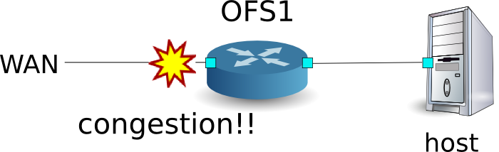
以下のようなトポロジを想定し、スイッチにQueueの設定とルールを追加し適切な帯域幅を割り当てる例を紹介します。また、OFS1のWAN側インターフェースでトラフィックシェーピングを行う場合を想定しています。
環境構築
まずはMininet上に環境を構築します。mnコマンドのパラメータは以下のようになります。
| パラメータ | 値 | 説明 |
|---|---|---|
| mac | なし | 自動的にホストのMACアドレスをセットする |
| switch | ovsk | Open vSwitchを使用する |
| controller | remote | OpenFlowコントローラは外部のものを利用する |
| x | なし | xtermを起動する |
実行例は以下のようになります。
$ sudo mn --mac --switch ovsk --controller remote -x
*** Creating network
*** Adding controller
Unable to contact the remote controller at 127.0.0.1:6633
*** Adding hosts:
h1 h2
*** Adding switches:
s1
*** Adding links:
(h1, s1) (h2, s1)
*** Configuring hosts
h1 h2
*** Running terms on localhost:10.0
*** Starting controller
*** Starting 1 switches
s1
*** Starting CLI:
mininet>
また、コントローラ用のxtermをもうひとつ起動しておきます。
mininet> xterm c0
mininet>
続いて、スイッチで使用するOpenFlowのバージョンを1.3に設定します。また、OVSDBへアクセスを行うため、6632ポートで待ち受けるように設定します。
switch: s1 (root):
# ovs-vsctl set Bridge s1 protocols=OpenFlow13
# ovs-vsctl set-manager ptcp:6632
続いて、「スイッチングハブ」で使用したsimple_switch_13.pyを変更します。rest_qos.pyはフローテーブルのパイプライン上で処理される事を想定しているため、simple_switch_13.pyのフローエントリをtable id:1に登録するように変更します。
controller: c0 (root)
# sed '/OFPFlowMod(/,/)/s/)/, table_id=1)/' ryu/ryu/app/simple_switch_13.py > ryu/ryu/app/qos_simple_switch_13.py
# cd ryu/; python ./setup.py install
最後に、コントローラのxterm上でrest_qos、qos_simple_switch_13、rest_conf_switchを起動させます。
controller: c0 (root):
# ryu-manager ryu.app.rest_qos ryu.app.qos_simple_switch_13 ryu.app.rest_conf_switch
loading app ryu.app.rest_qos
loading app ryu.app.qos_simple_switch_13
loading app ryu.app.rest_conf_switch
loading app ryu.controller.ofp_handler
loading app ryu.controller.ofp_handler
loading app ryu.controller.ofp_handler
instantiating app None of DPSet
creating context dpset
instantiating app None of ConfSwitchSet
creating context conf_switch
creating context wsgi
instantiating app ryu.app.rest_conf_switch of ConfSwitchAPI
instantiating app ryu.app.qos_simple_switch_13 of SimpleSwitch13
instantiating app ryu.controller.ofp_handler of OFPHandler
instantiating app ryu.app.rest_qos of RestQoSAPI
(3519) wsgi starting up on http://0.0.0.0:8080/
Ryuとスイッチの間の接続に成功すると、次のメッセージが表示されます。
controller: c0 (root):
[QoS][INFO] dpid=0000000000000001: Join qos switch.
上記ログが表示されれば、準備完了です。
Queueの設定
スイッチにQueueを設定します。
| キューID | 最大レート | 最小レート |
|---|---|---|
| 0 | 500Kbps | - |
| 1 | (1Mbps) | 800Kbps |
注釈
以降の説明で使用するREST APIの詳細は、章末の「REST API一覧」を参照してください。
まずは、OVSDBへアクセスする為の設定を行います。
Node: c0 (root):
# curl -X PUT -d '"tcp:127.0.0.1:6632"' http://localhost:8080/v1.0/conf/switches/0000000000000001/ovsdb_addr
#
続いて、Queueの設定を行います。
# curl -X POST -d '{"port_name": "s1-eth1", "type": "linux-htb", "max_rate": "1000000", "queues": [{"max_rate": "500000"}, {"min_rate": "800000"}]}' http://localhost:8080/qos/queue/0000000000000001
  [
    {
      "switch_id": "0000000000000001",
      "command_result": {
        "result": "success",
        "details": {
          "0": {
            "config": {
              "max-rate": "500000"
            }
          },
          "1": {
            "config": {
              "min-rate": "800000"
            }
          }
        }
      }
    }
  ]
注釈
RESTコマンドの実行結果は見やすいように整形しています。
QoSの設定
以下の通りスイッチにフローの設定を行います。
| (優先度) | 宛先 | 宛先ポート | プロトコル | Queue ID | (QoS ID) |
|---|---|---|---|---|---|
| 1 | 10.0.0.1 | 5002 | UDP | 1 | 1 |
Node: c0 (root):
# curl -X POST -d '{"match": {"nw_dst": "10.0.0.1", "nw_proto": "UDP", "tp_dst": "5002"}, "actions":{"queue": "1"}}' http://localhost:8080/qos/rules/0000000000000001
  [
    {
      "switch_id": "0000000000000001",
      "command_result": [
        {
          "result": "success",
          "details": "QoS added. : qos_id=1"
        }
      ]
    }
  ]
設定内容の確認
各スイッチに設定された内容を確認します。
Node: c0 (root):
# curl -X GET http://localhost:8080/qos/rules/0000000000000001
  [
    {
      "switch_id": "0000000000000001",
      "command_result": [
        {
          "qos": [
            {
              "priority": 1,
              "dl_type": "IPv4",
              "nw_proto": "UDP",
              "tp_dst": 5002,
              "qos_id": 1,
              "nw_dst": "10.0.0.1",
              "actions": [
                {
                  "queue": "1"
                }
              ]
            }
          ]
        }
      ]
    }
  ]
帯域計測
この状態で、iperfで帯域計測をしてみます。h1はサーバとなりプロトコルはUDPで5001ポートと5002ポートで待ち受けます。h2はクライアントとなりh1の5001ポートに1MbpsのUDPトラフィック、h1の5002ポートに1MbpsのUDPトラフィックを送出します。
注釈
以降の例では、帯域計測にiperf(http://iperf.fr/)を使用します。iperfのインストール、使用方法については、本稿では解説しません。
まず、h1、h2のターミナルを一つずつ起動します。
mininet> xterm h1
mininet> xterm h2
Node: h1(1) (root):
# iperf -s -u -i 1 -p 5001
...
Node: h1(2) (root):
# iperf -s -u -i 1 -p 5002
...
Node: h2(1) (root):
# iperf -c 10.0.0.1 -p 5001 -u -b 1M
...
Node: h2(2) (root):
# iperf -c 10.0.0.1 -p 5002 -u -b 1M
...
Node: h1(1) (root):
[  4] local 10.0.0.1 port 5001 connected with 10.0.0.2 port 50375
[ ID] Interval       Transfer     Bandwidth        Jitter   Lost/Total Datagrams
[  4]  0.0- 1.0 sec  60.3 KBytes   494 Kbits/sec  12.208 ms    4/   42 (9.5%)
[  4]  0.0- 1.0 sec  4 datagrams received out-of-order
[  4]  1.0- 2.0 sec  58.9 KBytes   482 Kbits/sec  12.538 ms    0/   41 (0%)
[  4]  2.0- 3.0 sec  58.9 KBytes   482 Kbits/sec  12.494 ms    0/   41 (0%)
[  4]  3.0- 4.0 sec  58.9 KBytes   482 Kbits/sec  12.625 ms    0/   41 (0%)
[  4]  4.0- 5.0 sec  58.9 KBytes   482 Kbits/sec  12.576 ms    0/   41 (0%)
[  4]  5.0- 6.0 sec  58.9 KBytes   482 Kbits/sec  12.561 ms    0/   41 (0%)
[  4]  6.0- 7.0 sec  11.5 KBytes  94.1 Kbits/sec  45.536 ms    0/    8 (0%)
[  4]  7.0- 8.0 sec  4.31 KBytes  35.3 Kbits/sec  92.790 ms    0/    3 (0%)
[  4]  8.0- 9.0 sec  4.31 KBytes  35.3 Kbits/sec  135.391 ms    0/    3 (0%)
[  4]  9.0-10.0 sec  4.31 KBytes  35.3 Kbits/sec  167.045 ms    0/    3 (0%)
[  4] 10.0-11.0 sec  4.31 KBytes  35.3 Kbits/sec  193.006 ms    0/    3 (0%)
[  4] 11.0-12.0 sec  4.31 KBytes  35.3 Kbits/sec  213.944 ms    0/    3 (0%)
[  4] 12.0-13.0 sec  4.31 KBytes  35.3 Kbits/sec  231.981 ms    0/    3 (0%)
[  4] 13.0-14.0 sec  4.31 KBytes  35.3 Kbits/sec  249.758 ms    0/    3 (0%)
[  4] 14.0-15.0 sec  4.31 KBytes  35.3 Kbits/sec  261.139 ms    0/    3 (0%)
[  4] 15.0-16.0 sec  4.31 KBytes  35.3 Kbits/sec  269.879 ms    0/    3 (0%)
[  4] 16.0-17.0 sec  12.9 KBytes   106 Kbits/sec  204.755 ms    0/    9 (0%)
[  4] 17.0-18.0 sec  58.9 KBytes   482 Kbits/sec  26.214 ms    0/   41 (0%)
[  4] 18.0-19.0 sec  58.9 KBytes   482 Kbits/sec  13.485 ms    0/   41 (0%)
[  4] 19.0-20.0 sec  58.9 KBytes   482 Kbits/sec  12.690 ms    0/   41 (0%)
[  4] 20.0-21.0 sec  58.9 KBytes   482 Kbits/sec  12.498 ms    0/   41 (0%)
[  4] 21.0-22.0 sec  58.9 KBytes   482 Kbits/sec  12.601 ms    0/   41 (0%)
[  4] 22.0-23.0 sec  60.3 KBytes   494 Kbits/sec  12.640 ms    0/   42 (0%)
[  4] 23.0-24.0 sec  58.9 KBytes   482 Kbits/sec  12.508 ms    0/   41 (0%)
[  4] 24.0-25.0 sec  58.9 KBytes   482 Kbits/sec  12.578 ms    0/   41 (0%)
[  4] 25.0-26.0 sec  58.9 KBytes   482 Kbits/sec  12.541 ms    0/   41 (0%)
[  4] 26.0-27.0 sec  58.9 KBytes   482 Kbits/sec  12.539 ms    0/   41 (0%)
[  4] 27.0-28.0 sec  58.9 KBytes   482 Kbits/sec  12.578 ms    0/   41 (0%)
[  4] 28.0-29.0 sec  58.9 KBytes   482 Kbits/sec  12.527 ms    0/   41 (0%)
[  4] 29.0-30.0 sec  58.9 KBytes   482 Kbits/sec  12.542 ms    0/   41 (0%)
[  4]  0.0-30.6 sec  1.19 MBytes   327 Kbits/sec  12.562 ms    4/  852 (0.47%)
[  4]  0.0-30.6 sec  4 datagrams received out-of-order
Node: h1(2) (root):
[  4] local 10.0.0.1 port 5002 connected with 10.0.0.2 port 60868
[ ID] Interval       Transfer     Bandwidth        Jitter   Lost/Total Datagrams
[  4]  0.0- 1.0 sec   112 KBytes   917 Kbits/sec   4.288 ms    0/   78 (0%)
[  4]  1.0- 2.0 sec   115 KBytes   941 Kbits/sec   4.168 ms    0/   80 (0%)
[  4]  2.0- 3.0 sec   115 KBytes   941 Kbits/sec   4.454 ms    0/   80 (0%)
[  4]  3.0- 4.0 sec   113 KBytes   929 Kbits/sec   4.226 ms    0/   79 (0%)
[  4]  4.0- 5.0 sec   113 KBytes   929 Kbits/sec   4.096 ms    0/   79 (0%)
[  4]  5.0- 6.0 sec   113 KBytes   929 Kbits/sec   4.225 ms    0/   79 (0%)
[  4]  6.0- 7.0 sec   113 KBytes   929 Kbits/sec   4.055 ms    0/   79 (0%)
[  4]  7.0- 8.0 sec   113 KBytes   929 Kbits/sec   4.241 ms    0/   79 (0%)
[  4]  8.0- 9.0 sec   115 KBytes   941 Kbits/sec   3.886 ms    0/   80 (0%)
[  4]  9.0-10.0 sec   112 KBytes   917 Kbits/sec   3.969 ms    0/   78 (0%)
[  4]  0.0-10.8 sec  1.19 MBytes   931 Kbits/sec   4.287 ms    0/  852 (0%)
結果から分かる通りに5001ポート宛のトラフィックは帯域制限により500Kbps以下にシェーピングされ、5002ポート宛のトラフィックは800kbpsの帯域保証が行われていることが分かります。
DiffServによるQoSの動作例
先ほどの例ではフロー毎にQoSを行いましたが、きめ細かい制御ができる反面、扱うフローが増加するに伴い、帯域制御を行う各スイッチに設定するフローも増加し、スケーラブルではありません。そこでフロー毎にQoSを行うのではなく、DiffServドメインの入り口のルータでフローをいくつかのクラスに分け、クラス毎の制御を行うDiffServを適用します。DiffServではIPヘッダのToSフィールド内の6ビットのDSCP値を使用し、DSCP値により定義されるPHBに従って転送することで、QoSを実現します。
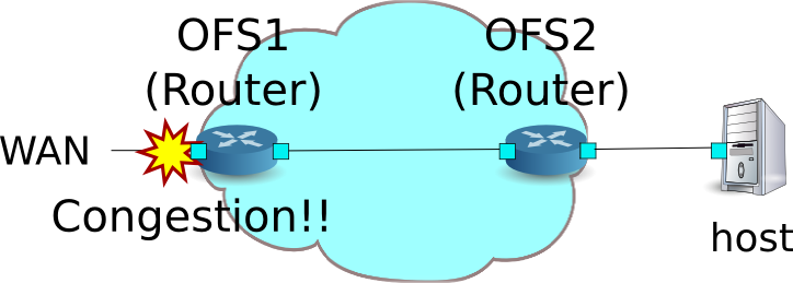
以下のようなトポロジを想定し、スイッチ(ルータ)OFS1にQueueの設定とクラスに応じた帯域制御を設定し、ルータOFS2にはフローに応じたDSCP値をマーキングを行うルールを適用する例を紹介します。また、OFS1のWAN側インターフェースでトラフィックシェーピングを行う場合を想定しています。
環境構築
まずはMininet上に環境を構築します。mnコマンドのパラメータは以下のようになります。
| パラメータ | 値 | 説明 |
|---|---|---|
| topo | linear,2 | 2台のスイッチが直列に接続されているトポロジ |
| mac | なし | 自動的にホストのMACアドレスをセットする |
| switch | ovsk | Open vSwitchを使用する |
| controller | remote | OpenFlowコントローラは外部のものを利用する |
| x | なし | xtermを起動する |
実行例は以下のようになります。
$ sudo mn --topo linear,2 --mac --switch ovsk --controller remote -x
*** Creating network
*** Adding controller
Unable to contact the remote controller at 127.0.0.1:6633
*** Adding hosts:
h1 h2
*** Adding switches:
s1
*** Adding links:
(h1, s1) (h2, s1)
*** Configuring hosts
h1 h2
*** Running terms on localhost:10.0
*** Starting controller
*** Starting 1 switches
s1
*** Starting CLI:
mininet>
また、コントローラ用のxtermをもうひとつ起動しておきます。
mininet> xterm c0
mininet>
続いて、スイッチで使用するOpenFlowのバージョンを1.3に設定します。また、OVSDBへアクセスを行うため、6632ポートで待ち受けるように設定します。
switch: s1 (root):
# ovs-vsctl set Bridge s1 protocols=OpenFlow13
# ovs-vsctl set-manager ptcp:6632
switch: s2 (root):
# ovs-vsctl set Bridge s2 protocols=OpenFlow13
その後、各ホストで自動的に割り当てられているIPアドレスを削除し、新たにIPアドレスを設定します。
host: h1:
# ip addr del 10.0.0.1/8 dev h1-eth0
# ip addr add 172.16.20.10/24 dev h1-eth0
host: h2:
# ip addr del 10.0.0.2/8 dev h2-eth0
# ip addr add 172.16.10.10/24 dev h2-eth0
続いて、「ルータ」で使用したrest_router.pyを変更します。rest_qos.pyはフローテーブルのパイプライン上で処理される事を想定しているため、rest_router.pyのフローエントリをtable id:1に登録するように変更します。
controller: c0 (root):
# sed '/OFPFlowMod(/,/)/s/0, cmd/1, cmd/' ryu/ryu/app/rest_router.py > ryu/ryu/app/qos_rest_router.py
# cd ryu/; python ./setup.py install
最後に、コントローラのxterm上でrest_qos、qos_rest_router、rest_conf_switchを起動させます。
controller: c0 (root):
# ryu-manager ryu.app.rest_qos ryu.app.qos_rest_router ryu.app.rest_conf_switch
loading app ryu.app.rest_qos
loading app ryu.app.qos_rest_router
loading app ryu.app.rest_conf_switch
loading app ryu.controller.ofp_handler
loading app ryu.controller.ofp_handler
loading app ryu.controller.ofp_handler
loading app ryu.controller.ofp_handler
instantiating app None of DPSet
creating context dpset
instantiating app None of ConfSwitchSet
creating context conf_switch
creating context wsgi
instantiating app ryu.app.rest_conf_switch of ConfSwitchAPI
instantiating app ryu.app.qos_rest_router of RestRouterAPI
instantiating app ryu.controller.ofp_handler of OFPHandler
instantiating app ryu.app.rest_qos of RestQoSAPI
(4687) wsgi starting up on http://0.0.0.0:8080/
Ryuとスイッチの間の接続に成功すると、次のメッセージが表示されます。
controller: c0 (root):
[RT][INFO] switch_id=0000000000000002: Set SW config for TTL error packet in.
[RT][INFO] switch_id=0000000000000002: Set ARP handling (packet in) flow [cookie=0x0]
[RT][INFO] switch_id=0000000000000002: Set L2 switching (normal) flow [cookie=0x0]
[RT][INFO] switch_id=0000000000000002: Set default route (drop) flow [cookie=0x0]
[RT][INFO] switch_id=0000000000000002: Start cyclic routing table update.
[RT][INFO] switch_id=0000000000000002: Join as router.
[QoS][INFO] dpid=0000000000000002: Join qos switch.
[RT][INFO] switch_id=0000000000000001: Set SW config for TTL error packet in.
[RT][INFO] switch_id=0000000000000001: Set ARP handling (packet in) flow [cookie=0x0]
[RT][INFO] switch_id=0000000000000001: Set L2 switching (normal) flow [cookie=0x0]
[RT][INFO] switch_id=0000000000000001: Set default route (drop) flow [cookie=0x0]
[RT][INFO] switch_id=0000000000000001: Start cyclic routing table update.
[RT][INFO] switch_id=0000000000000001: Join as router.
[QoS][INFO] dpid=0000000000000001: Join qos switch.
上記ログが表示されれば、準備完了です。
Queueの設定
| キューID | 最大レート | 最小レート | クラス |
|---|---|---|---|
| 0 | 1Mbps | - | Default |
| 1 | (1Mbps) | 200Kbps | AF3 |
| 2 | (1Mbps) | 500Kbps | AF4 |
注釈
以降の説明で使用するREST APIの詳細は、章末の「REST API一覧」を参照してください。
まずは、OVSDBへアクセスする為の設定を行います。
Node: c0 (root):
# curl -X PUT -d '"tcp:127.0.0.1:6632"' http://localhost:8080/v1.0/conf/switches/0000000000000001/ovsdb_addr
#
続いて、Queueの設定を行います。
# curl -X POST -d '{"port_name": "s1-eth1", "type": "linux-htb", "max_rate": "1000000", "queues":[{"max_rate": "1000000"}, {"min_rate": "200000"}, {"min_rate": "500000"}]}' http://localhost:8080/qos/queue/0000000000000001
  [
    {
      "switch_id": "0000000000000001",
      "command_result": {
        "result": "success",
        "details": {
          "0": {
            "config": {
              "max-rate": "1000000"
            }
          },
          "1": {
            "config": {
              "min-rate": "200000"
            }
          },
          "2": {
            "config": {
              "min-rate": "500000"
            }
          }
        }
      }
    }
  ]
注釈
RESTコマンドの実行結果は見やすいように整形しています。
ルータの設定
各ルータへアドレスの設定、デフォルトルートの設定を行います。
# curl -X POST -d '{"address": "172.16.20.1/24"}' http://localhost:8080/router/0000000000000001
  [
    {
      "switch_id": "0000000000000001",
      "command_result": [
        {
          "result": "success",
          "details": "Add address [address_id=1]"
        }
      ]
    }
  ]

# curl -X POST -d '{"address": "172.16.30.10/24"}' http://localhost:8080/router/0000000000000001
  [
    {
      "switch_id": "0000000000000001",
      "command_result": [
        {
          "result": "success",
          "details": "Add address [address_id=2]"
        }
      ]
    }
  ]

# curl -X POST -d '{"gateway": "172.16.30.1"}' http://localhost:8080/router/0000000000000001
  [
    {
      "switch_id": "0000000000000001",
      "command_result": [
        {
          "result": "success",
          "details": "Add route [route_id=1]"
        }
      ]
    }
  ]

# curl -X POST -d '{"address": "172.16.10.1/24"}' http://localhost:8080/router/0000000000000002
  [
    {
      "switch_id": "0000000000000002",
      "command_result": [
        {
          "result": "success",
          "details": "Add address [address_id=1]"
        }
      ]
    }
  ]

# curl -X POST -d '{"address": "172.16.30.1/24"}' http://localhost:8080/router/0000000000000002
  [
    {
      "switch_id": "0000000000000002",
      "command_result": [
        {
          "result": "success",
          "details": "Add address [address_id=2]"
        }
      ]
    }
  ]

# curl -X POST -d '{"gateway": "172.16.30.10"}' http://localhost:8080/router/0000000000000002
  [
    {
      "switch_id": "0000000000000002",
      "command_result": [
        {
          "result": "success",
          "details": "Add route [route_id=1]"
        }
      ]
    }
  ]
...
ルータへのIPアドレスの設定ができたので、各ホストにデフォルトゲートウェイとして登録します。
host: h1:
# ip route add default via 172.16.20.1
host: h2:
# ip route add default via 172.16.10.1
QoSの設定
以下の通りルータ(s1)にDSCP値に応じた制御を行うフローを設定します。
| (優先度) | DSCP | キューID | (QoS ID) |
|---|---|---|---|
| 1 | 26(AF31) | 1 | 1 |
| 1 | 34(AF41) | 2 | 2 |
Node: c0 (root):
# curl -X POST -d '{"match": {"ip_dscp": "26"}, "actions":{"queue": "1"}}' http://localhost:8080/qos/rules/0000000000000001
  [
    {
      "switch_id": "0000000000000001",
      "command_result": [
        {
          "result": "success",
          "details": "QoS added. : qos_id=1"
        }
      ]
    }
  ]

# curl -X POST -d '{"match": {"ip_dscp": "34"}, "actions":{"queue": "2"}}' http://localhost:8080/qos/rules/0000000000000001
  [
    {
      "switch_id": "0000000000000001",
      "command_result": [
        {
          "result": "success",
          "details": "QoS added. : qos_id=2"
        }
      ]
    }
  ]
以下の通りルータ(s2)にマーキングを行うフローの設定を行います。
| (優先度) | 宛先 | 宛先ポート | プロトコル | DSCP | (QoS ID) |
|---|---|---|---|---|---|
| 1 | 172.16.20.10 | 5002 | UDP | 26(AF31) | 1 |
| 1 | 172.16.20.10 | 5003 | UDP | 34(AF41) | 2 |
Node: c0 (root):
# curl -X POST -d '{"match": {"nw_dst": "172.16.20.10", "nw_proto": "UDP", "tp_dst": "5002"}, "actions":{"mark": "26"}}' http://localhost:8080/qos/rules/0000000000000002
  [
    {
      "switch_id": "0000000000000002",
      "command_result": [
        {
          "result": "success",
          "details": "QoS added. : qos_id=1"
        }
      ]
    }
  ]

# curl -X POST -d '{"match": {"nw_dst": "172.16.20.10", "nw_proto": "UDP", "tp_dst": "5003"}, "actions":{"mark": "34"}}' http://localhost:8080/qos/rules/0000000000000002
  [
    {
      "switch_id": "0000000000000002",
      "command_result": [
        {
          "result": "success",
          "details": "QoS added. : qos_id=2"
        }
      ]
    }
  ]
設定内容の確認
各スイッチに設定された内容を確認します。
Node: c0 (root):
# curl -X GET http://localhost:8080/qos/rules/0000000000000001
  [
    {
      "switch_id": "0000000000000001",
      "command_result": [
        {
          "qos": [
            {
              "priority": 1,
              "dl_type": "IPv4",
              "ip_dscp": 34,
              "actions": [
                {
                  "queue": "2"
                }
              ],
              "qos_id": 2
            },
            {
              "priority": 1,
              "dl_type": "IPv4",
              "ip_dscp": 26,
              "actions": [
                {
                  "queue": "1"
                }
              ],
              "qos_id": 1
            }
          ]
        }
      ]
    }
  ]

# curl -X GET http://localhost:8080/qos/rules/0000000000000002
  [
    {
      "switch_id": "0000000000000002",
      "command_result": [
        {
          "qos": [
            {
              "priority": 1,
              "dl_type": "IPv4",
              "nw_proto": "UDP",
              "tp_dst": 5002,
              "qos_id": 1,
              "nw_dst": "172.16.20.10",
              "actions": [
                {
                  "mark": "26"
                }
              ]
            },
            {
              "priority": 1,
              "dl_type": "IPv4",
              "nw_proto": "UDP",
              "tp_dst": 5003,
              "qos_id": 2,
              "nw_dst": "172.16.20.10",
              "actions": [
                {
                  "mark": "34"
                }
              ]
            }
          ]
        }
      ]
    }
  ]
帯域計測
この状態で、iperfで帯域計測をしてみます。h1はサーバとなりプロトコルはUDPで5001ポートと5002ポートと5003ポートで待ち受けます。h2はクライアントとなりh1の5001ポートに1MbpsのUDPトラフィック、h1の5002ポートに300KbpsのUDPトラフィック、h1の5003ポートに600KbpsのUDPトラフィックを送出します。
まず、h2のターミナルを2つ起動します。
mininet> xterm h2
mininet> xterm h2
Node: h1(1) (root):
# iperf -s -u -p 5002 &
...
# iperf -s -u -p 5003 &
...
# iperf -s -u -i 1 5001
------------------------------------------------------------
Server listening on UDP port 5001
Receiving 1470 byte datagrams
UDP buffer size:  208 KByte (default)
------------------------------------------------------------
Node: h2(1) (root):
# iperf -c 172.16.20.10 -p 5001 -u -b 1M
...
Node: h2(2) (root):
# iperf -c 172.16.20.10 -p 5002 -u -b 300K
------------------------------------------------------------
Client connecting to 172.16.20.10, UDP port 5002
Sending 1470 byte datagrams
UDP buffer size:  208 KByte (default)
------------------------------------------------------------
[  4] local 172.16.10.10 port 44077 connected with 172.16.20.10 port 5002
[ ID] Interval       Transfer     Bandwidth
[  4]  0.0-10.1 sec   369 KBytes   300 Kbits/sec
[  4] Sent 257 datagrams
[  4] Server Report:
[  4]  0.0-10.2 sec   369 KBytes   295 Kbits/sec  17.379 ms    0/  257 (0%)
Node: h2(3) (root):
# iperf -c 172.16.20.10 -p 5003 -u -b 600K
------------------------------------------------------------
Client connecting to 172.16.20.10, UDP port 5003
Sending 1470 byte datagrams
UDP buffer size:  208 KByte (default)
------------------------------------------------------------
[  4] local 172.16.10.10 port 59280 connected with 172.16.20.10 port 5003
[ ID] Interval       Transfer     Bandwidth
[  4]  0.0-10.0 sec   735 KBytes   600 Kbits/sec
[  4] Sent 512 datagrams
[  4] Server Report:
[  4]  0.0-10.0 sec   735 KBytes   600 Kbits/sec   5.401 ms    0/  512 (0%)
Node: h1(1) (root):
[  4] local 172.16.20.10 port 5001 connected with 172.16.10.10 port 37329
[ ID] Interval       Transfer     Bandwidth        Jitter   Lost/Total Datagrams
[  4]  0.0- 1.0 sec   119 KBytes   976 Kbits/sec   0.639 ms    0/   83 (0%)
[  4]  1.0- 2.0 sec   118 KBytes   964 Kbits/sec   0.680 ms    0/   82 (0%)
[  4]  2.0- 3.0 sec  87.6 KBytes   717 Kbits/sec   5.817 ms    0/   61 (0%)
[  4]  3.0- 4.0 sec  81.8 KBytes   670 Kbits/sec   5.700 ms    0/   57 (0%)
[  4]  4.0- 5.0 sec  66.0 KBytes   541 Kbits/sec  12.772 ms    0/   46 (0%)
[  4]  5.0- 6.0 sec  8.61 KBytes  70.6 Kbits/sec  60.590 ms    0/    6 (0%)
[  4]  6.0- 7.0 sec  8.61 KBytes  70.6 Kbits/sec  89.968 ms    0/    6 (0%)
[  4]  7.0- 8.0 sec  8.61 KBytes  70.6 Kbits/sec  108.364 ms    0/    6 (0%)
[  4]  8.0- 9.0 sec  10.0 KBytes  82.3 Kbits/sec  125.635 ms    0/    7 (0%)
[  4]  9.0-10.0 sec  8.61 KBytes  70.6 Kbits/sec  130.604 ms    0/    6 (0%)
[  4] 10.0-11.0 sec  8.61 KBytes  70.6 Kbits/sec  140.192 ms    0/    6 (0%)
[  4] 11.0-12.0 sec  8.61 KBytes  70.6 Kbits/sec  144.411 ms    0/    6 (0%)
[  4] 12.0-13.0 sec  28.7 KBytes   235 Kbits/sec  63.964 ms    0/   20 (0%)
[  4] 13.0-14.0 sec  44.5 KBytes   365 Kbits/sec  26.721 ms    0/   31 (0%)
[  4] 14.0-15.0 sec  57.4 KBytes   470 Kbits/sec   9.396 ms    0/   40 (0%)
[  4] 15.0-16.0 sec   118 KBytes   964 Kbits/sec   0.956 ms    0/   82 (0%)
[  4] 16.0-17.0 sec   119 KBytes   976 Kbits/sec   0.820 ms    0/   83 (0%)
[  4] 17.0-18.0 sec   118 KBytes   964 Kbits/sec   0.741 ms    0/   82 (0%)
[  4] 18.0-19.0 sec   118 KBytes   964 Kbits/sec   0.839 ms    0/   82 (0%)
[  4]  0.0-19.7 sec  1.19 MBytes   508 Kbits/sec   0.981 ms    0/  852 (0%)
AF41にマーキングされているトラフィックは500Kbpsの帯域保証がされ、AF31にマーキングされているトラフィックは200Kbpsの帯域保証がされています。一方、ベストエフォートのトラフィックはAFにマーキングされているトラフィックが流れている間は帯域幅が狭められているのが分かります。このようにDiffServによりQoSを実現できることが確認できました。
Meter Tableを使用したQoSの動作例
OpenFlow 1.3よりMeter Tableが導入されOpenFlowでトラフィックのポリシングが可能となりました。Meter Tableの利用例について紹介します。こちらの例では、Meter TableをサポートするOpenFlow Switchのofsoftswitch13(https://github.com/CPqD/ofsoftswitch13)を使用します。
注釈
ofsoftswitch13のインストール手順などについては本稿では解説しません。参考:(https://github.com/CPqD/ofsoftswitch13/wiki/OpenFlow-1.3-Tutorial)
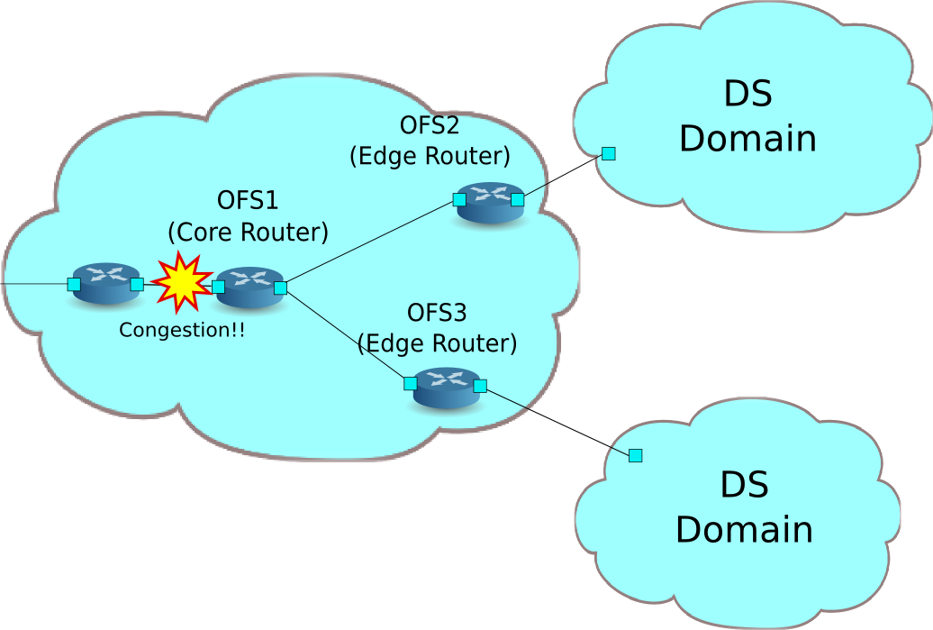
以下のように複数のDiffServドメイン(DSドメイン)により構成されているネットワークを想定します。DSドメインの境界に位置するルータ(エッジルータ)によってメータリングが行われ、指定帯域を超えるトラフィックは再マーキングされます。通常再マーキングされたパケットは優先的に破棄されるか、優先順位の低いクラスとして扱われます。例では、AF1クラスに対して800Kbpsの帯域保証を行い、各DSドメインから流入するAF11のトラフィックの400Kbpsを契約帯域とし、それ以上は超過トラフィックとしてパケットはAF12に再マーキングされます。ただし、AF12はベストエフォートのトラフィックよりは保証されるように設定しています。
環境構築
まずはMininet上に環境を構築します。トポロジの作成はPythonスクリプトで行います。
ソース名:qos_sample_topology.py
from mininet.net import Mininet
from mininet.cli import CLI
from mininet.topo import Topo
from mininet.node import UserSwitch
from mininet.node import RemoteController

class SliceableSwitch(UserSwitch):
    def __init__(self, name, **kwargs):
        UserSwitch.__init__(self, name, '', **kwargs)

class MyTopo(Topo):
    def __init__( self ):
        "Create custom topo."
        # Initialize topology
        Topo.__init__( self )
        # Add hosts and switches
        host01 = self.addHost('h1')
        host02 = self.addHost('h2')
        host03 = self.addHost('h3')
        switch01 = self.addSwitch('s1')
        switch02 = self.addSwitch('s2')
        switch03 = self.addSwitch('s3')
        # Add links
        self.addLink(host01, switch01)
        self.addLink(host02, switch02)
        self.addLink(host03, switch03)
        self.addLink(switch01, switch02)
        self.addLink(switch01, switch03)

def run(net):
    s1 = net.getNodeByName('s1')
    s1.cmdPrint('dpctl unix:/tmp/s1 queue-mod 1 1 80')
    s1.cmdPrint('dpctl unix:/tmp/s1 queue-mod 1 2 120')
    s1.cmdPrint('dpctl unix:/tmp/s1 queue-mod 1 3 800')

def genericTest(topo):
    net = Mininet(topo=topo, switch=SliceableSwitch,
        controller=RemoteController)
    net.start()
    run(net)
    CLI(net)
    net.stop()

def main():
    topo = MyTopo()
    genericTest(topo)

if __name__ == '__main__':
    main()
注釈
あらかじめofsoftswitch13のリンクスピードを1Mbpsに変更します。
まず、ofsoftswitch13のソースコードを修正します。
$ cd ofsoftswitch13
$ gedit lib/netdev.c
lib/netdev.c:
644           if (ecmd.autoneg) {
645               netdev->curr |= OFPPF_AUTONEG;
646           }
647
648 -         netdev->speed = ecmd.speed;
649 +         netdev->speed = 1;  /* Fix to 1Mbps link */
650
651       } else {
652           VLOG_DBG(LOG_MODULE, "ioctl(SIOCETHTOOL) failed: %s", strerror(errno));
653       }
そして、ofsoftswitch13を再インストールします。
$ make clean
$ ./boot.sh
$ ./configure
$ make
$ sudo make install
実行例は以下の通りになります
$ curl -O https://raw.githubusercontent.com/osrg/ryu-book/master/sources/qos_sample_topology.py
$ sudo python ./qos_sample_topology.py
Unable to contact the remote controller at 127.0.0.1:6633
mininet>
また、コントローラ用のxtermを2つ起動しておきます。
mininet> xterm c0
mininet> xterm c0
mininet>
続いて、「スイッチングハブ」で使用したsimple_switch_13.pyを変更します。rest_qos.pyはフローテーブルのパイプライン上で処理される事を想定しているため、simple_switch_13.pyのフローエントリをtable id:1に登録するように変更します。
controller: c0 (root)
# sed '/OFPFlowMod(/,/)/s/)/, table_id=1)/' ryu/ryu/app/simple_switch_13.py > ryu/ryu/app/qos_simple_switch_13.py
# cd ryu/; python ./setup.py install
最後に、コントローラのxterm上でrest_qos、qos_simple_switch_13を起動させます。
controller: c0 (root):
# ryu-manager ryu.app.rest_qos ryu.app.qos_simple_switch_13
loading app ryu.app.rest_qos
loading app ryu.app.qos_simple_switch_13
loading app ryu.controller.ofp_handler
loading app ryu.controller.ofp_handler
loading app ryu.controller.ofp_handler
instantiating app None of DPSet
creating context dpset
instantiating app None of ConfSwitchSet
creating context conf_switch
creating context wsgi
instantiating app ryu.app.qos_simple_switch_13 of SimpleSwitch13
instantiating app ryu.controller.ofp_handler of OFPHandler
instantiating app ryu.app.rest_qos of RestQoSAPI
(2348) wsgi starting up on http://0.0.0.0:8080/
Ryuとスイッチの間の接続に成功すると、次のメッセージが表示されます。
controller: c0 (root):
[QoS][INFO] dpid=0000000000000003: Join qos switch.
[QoS][INFO] dpid=0000000000000001: Join qos switch.
[QoS][INFO] dpid=0000000000000002: Join qos switch.
...
QoSの設定
以下の通りスイッチ(s1)にDSCP値に応じた制御を行うフローを設定します。
| (優先度) | DSCP | キューID | (QoS ID) |
|---|---|---|---|
| 1 | 0 (BE) | 1 | 1 |
| 1 | 12(AF12) | 2 | 2 |
| 1 | 10(AF11) | 3 | 3 |
Node: c0 (root):
# curl -X POST -d '{"match": {"ip_dscp": "0", "in_port": "2"}, "actions":{"queue": "1"}}' http://localhost:8080/qos/rules/0000000000000001
  [
    {
      "switch_id": "0000000000000001",
      "command_result": [
        {
          "result": "success",
          "details": "QoS added. : qos_id=1"
        }
      ]
    }
  ]

# curl -X POST -d '{"match": {"ip_dscp": "10", "in_port": "2"}, "actions":{"queue": "3"}}' http://localhost:8080/qos/rules/0000000000000001
  [
    {
      "switch_id": "0000000000000001",
      "command_result": [
        {
          "result": "success",
          "details": "QoS added. : qos_id=2"
        }
      ]
    }
  ]

# curl -X POST -d '{"match": {"ip_dscp": "12", "in_port": "2"}, "actions":{"queue": "2"}}' http://localhost:8080/qos/rules/0000000000000001
  [
    {
      "switch_id": "0000000000000001",
      "command_result": [
        {
          "result": "success",
          "details": "QoS added. : qos_id=3"
        }
      ]
    }
  ]

# curl -X POST -d '{"match": {"ip_dscp": "0", "in_port": "3"}, "actions":{"queue": "1"}}' http://localhost:8080/qos/rules/0000000000000001
  [
    {
      "switch_id": "0000000000000001",
      "command_result": [
        {
          "result": "success",
          "details": "QoS added. : qos_id=4"
        }
      ]
    }
  ]

# curl -X POST -d '{"match": {"ip_dscp": "10", "in_port": "3"}, "actions":{"queue": "3"}}' http://localhost:8080/qos/rules/0000000000000001
  [
    {
      "switch_id": "0000000000000001",
      "command_result": [
        {
          "result": "success",
          "details": "QoS added. : qos_id=5"
        }
      ]
    }
  ]

# curl -X POST -d '{"match": {"ip_dscp": "12", "in_port": "3"}, "actions":{"queue": "2"}}' http://localhost:8080/qos/rules/0000000000000001
  [
    {
      "switch_id": "0000000000000001",
      "command_result": [
        {
          "result": "success",
          "details": "QoS added. : qos_id=6"
        }
      ]
    }
  ]
以下の通りスイッチ(s2、s3)にメータエントリーを設定します。
| (優先度) | DSCP | メータID | (QoS ID) |
|---|---|---|---|
| 1 | 10(AF11) | 1 | 1 |
| メータID | Flags | Bands |
|---|---|---|
| 1 | KBPS | type:DSCP_REMARK,rate:400000,prec_level:1 |
# curl -X POST -d '{"match": {"ip_dscp": "10"}, "actions":{"meter": "1"}}' http://localhost:8080/qos/rules/0000000000000002
  [
    {
      "switch_id": "0000000000000002",
      "command_result": [
        {
          "result": "success",
          "details": "QoS added. : qos_id=1"
        }
      ]
    }
  ]

# curl -X POST -d '{"meter_id": "1", "flags": "KBPS", "bands":[{"type":"DSCP_REMARK", "rate": "400", "prec_level": "1"}]}' http://localhost:8080/qos/meter/0000000000000002
  [
    {
      "switch_id": "0000000000000002",
      "command_result": [
        {
          "result": "success",
          "details": "Meter added. : Meter ID=1"
        }
      ]
    }
  ]

# curl -X POST -d '{"match": {"ip_dscp": "10"}, "actions":{"meter": "1"}}' http://localhost:8080/qos/rules/0000000000000003
[
  {
    "switch_id": "0000000000000003",
    "command_result": [
      {
        "result": "success",
        "details": "QoS added. : qos_id=1"
      }
    ]
  }
]

# curl -X POST -d '{"meter_id": "1", "flags": "KBPS", "bands":[{"type":"DSCP_REMARK", "rate": "400", "prec_level": "1"}]}' http://localhost:8080/qos/meter/0000000000000003
  [
    {
      "switch_id": "0000000000000003",
      "command_result": [
        {
          "result": "success",
          "details": "Meter added. : Meter ID=1"
        }
      ]
    }
  ]
設定内容の確認
各スイッチに設定された内容を確認します。
Node: c0 (root):
# curl -X GET http://localhost:8080/qos/rules/0000000000000001
  [
    {
      "switch_id": "0000000000000001",
      "command_result": [
        {
          "qos": [
            {
              "priority": 1,
              "dl_type": "IPv4",
              "actions": [
                {
                  "queue": "1"
                }
              ],
              "in_port": 2,
              "qos_id": 1
            },
            {
              "priority": 1,
              "dl_type": "IPv4",
              "actions": [
                {
                  "queue": "3"
                }
              ],
              "qos_id": 2,
              "in_port": 2,
              "ip_dscp": 10
            },
            {
              "priority": 1,
              "dl_type": "IPv4",
              "actions": [
                {
                  "queue": "2"
                }
              ],
              "qos_id": 3,
              "in_port": 2,
              "ip_dscp": 12
            },
            {
              "priority": 1,
              "dl_type": "IPv4",
              "actions": [
                {
                  "queue": "1"
                }
              ],
              "in_port": 3,
              "qos_id": 4
            },
            {
              "priority": 1,
              "dl_type": "IPv4",
              "actions": [
                {
                  "queue": "3"
                }
              ],
              "qos_id": 5,
              "in_port": 3,
              "ip_dscp": 10
            },
            {
              "priority": 1,
              "dl_type": "IPv4",
              "actions": [
                {
                  "queue": "2"
                }
              ],
              "qos_id": 6,
              "in_port": 3,
              "ip_dscp": 12
            }
          ]
        }
      ]
    }
  ]

# curl -X GET http://localhost:8080/qos/rules/0000000000000002
  [
    {
      "switch_id": "0000000000000002",
      "command_result": [
        {
          "qos": [
            {
              "priority": 1,
              "dl_type": "IPv4",
              "ip_dscp": 10,
              "actions": [
                {
                  "meter": "1"
                }
              ],
              "qos_id": 1
            }
          ]
        }
      ]
    }
  ]

# curl -X GET http://localhost:8080/qos/rules/0000000000000003
  [
    {
      "switch_id": "0000000000000003",
      "command_result": [
        {
          "qos": [
            {
              "priority": 1,
              "dl_type": "IPv4",
              "ip_dscp": 10,
              "actions": [
                {
                  "meter": "1"
                }
              ],
              "qos_id": 1
            }
          ]
        }
      ]
    }
  ]
帯域計測
この状態で、iperfで帯域計測をしてみます。h1はサーバとなりプロトコルはUDPで5001ポートと5002ポートと5003ポートで待ち受けます。h2、h3はクライアントとなりh1宛に各クラスのトラフィックを送出します。
まず、h1とh2で2つとh3の1つづつターミナルを起動します。
mininet> xterm h1
mininet> xterm h2
mininet> xterm h3
mininet> xterm h3
...
Node: h1(1) (root):
# iperf -s -u -p 5001 &
# iperf -s -u -p 5002 &
# iperf -s -u -p 5003 &
...
ベストエフォートと超過したAF11トラフィック
Node: h2 (root):
# iperf -c 10.0.0.1 -p 5001 -u -b 800K
------------------------------------------------------------
Client connecting to 10.0.0.1, UDP port 5001
Sending 1470 byte datagrams
UDP buffer size:  208 KByte (default)
------------------------------------------------------------
[  4] local 10.0.0.3 port 60324 connected with 10.0.0.1 port 5001
[ ID] Interval       Transfer     Bandwidth
[  4]  0.0-10.0 sec   979 KBytes   800 Kbits/sec
[  4] Sent 682 datagrams
[  4] Server Report:
[  4]  0.0-11.9 sec   650 KBytes   449 Kbits/sec  18.458 ms  229/  682 (34%)
Node: h3(1) (root):
# iperf -c 10.0.0.1 -p 5002 -u -b 600K --tos 0x28
------------------------------------------------------------
Client connecting to 10.0.0.1, UDP port 5002
Sending 1470 byte datagrams
UDP buffer size:  208 KByte (default)
------------------------------------------------------------
[  4] local 10.0.0.2 port 53661 connected with 10.0.0.1 port 5002
[ ID] Interval       Transfer     Bandwidth
[  4]  0.0-10.0 sec   735 KBytes   600 Kbits/sec
[  4] Sent 512 datagrams
[  4] Server Report:
[  4]  0.0-10.0 sec   735 KBytes   600 Kbits/sec   7.497 ms    6/  512 (1.2%)
[  4]  0.0-10.0 sec  6 datagrams received out-of-order
AF11のトラフィックが契約帯域400Kbpsを超過した場合でもベストエフォートのトラフィックより帯域が保証されている事が分かります。
AF11の超過トラフィックとベストエフォートとAF11の契約帯域内トラフィック
Node: h2 (root):
# iperf -c 10.0.0.1 -p 5001 -u -b 600K --tos 0x28
------------------------------------------------------------
Client connecting to 10.0.0.1, UDP port 5001
Sending 1470 byte datagrams
UDP buffer size:  208 KByte (default)
------------------------------------------------------------
[  4] local 10.0.0.2 port 49358 connected with 10.0.0.1 port 5001
[ ID] Interval       Transfer     Bandwidth
[  4]  0.0-10.0 sec   735 KBytes   600 Kbits/sec
[  4] Sent 512 datagrams
[  4] Server Report:
[  4]  0.0-10.0 sec   666 KBytes   544 Kbits/sec  500.361 ms   48/  512 (9.4%)
[  4]  0.0-10.0 sec  192 datagrams received out-of-order
Node: h3(1) (root):
# iperf -c 10.0.0.1 -p 5002 -u -b 500K
------------------------------------------------------------
Client connecting to 10.0.0.1, UDP port 5002
Sending 1470 byte datagrams
UDP buffer size:  208 KByte (default)
------------------------------------------------------------
[  4] local 10.0.0.3 port 42759 connected with 10.0.0.1 port 5002
[ ID] Interval       Transfer     Bandwidth
[  4]  0.0-10.0 sec   613 KBytes   500 Kbits/sec
[  4] Sent 427 datagrams
[  4] WARNING: did not receive ack of last datagram after 10 tries.
[  4] Server Report:
[  4]  0.0-14.0 sec   359 KBytes   210 Kbits/sec  102.479 ms  177/  427 (41%)
Node: h3(2) (root):
# iperf -c 10.0.0.1 -p 5003 -u -b 400K --tos 0x28
------------------------------------------------------------
Client connecting to 10.0.0.1, UDP port 5003
Sending 1470 byte datagrams
UDP buffer size:  208 KByte (default)
------------------------------------------------------------
[  4] local 10.0.0.3 port 35475 connected with 10.0.0.1 port 5003
[ ID] Interval       Transfer     Bandwidth
[  4]  0.0-10.1 sec   491 KBytes   400 Kbits/sec
[  4] Sent 342 datagrams
[  4] Server Report:
[  4]  0.0-10.5 sec   491 KBytes   384 Kbits/sec  15.422 ms    0/  342 (0%)
400Kbpsの契約帯域内のトラフィックはドロップされていない事がわかります。
AF11の超過トラフィックとAF11の超過トラフィック
Node: h2 (root):
# iperf -c 10.0.0.1 -p 5001 -u -b 600K --tos 0x28
------------------------------------------------------------
Client connecting to 10.0.0.1, UDP port 5001
Sending 1470 byte datagrams
UDP buffer size:  208 KByte (default)
------------------------------------------------------------
[  4] local 10.0.0.3 port 50761 connected with 10.0.0.1 port 5001
[ ID] Interval       Transfer     Bandwidth
[  4]  0.0-10.0 sec   735 KBytes   600 Kbits/sec
[  4] Sent 512 datagrams
[  4] Server Report:
[  4]  0.0-11.0 sec   673 KBytes   501 Kbits/sec  964.490 ms   43/  512 (8.4%)
[  4]  0.0-11.0 sec  95 datagrams received out-of-order
Node: h3(1) (root):
# iperf -c 10.0.0.1 -p 5002 -u -b 600K --tos 0x28
------------------------------------------------------------
Client connecting to 10.0.0.1, UDP port 5002
Sending 1470 byte datagrams
UDP buffer size:  208 KByte (default)
------------------------------------------------------------
[  4] local 10.0.0.2 port 53066 connected with 10.0.0.1 port 5002
[ ID] Interval       Transfer     Bandwidth
[  4]  0.0-10.0 sec   735 KBytes   600 Kbits/sec
[  4] Sent 512 datagrams
[  4] Server Report:
[  4]  0.0-10.6 sec   665 KBytes   515 Kbits/sec  897.126 ms   49/  512 (9.6%)
[  4]  0.0-10.6 sec  93 datagrams received out-of-order
超過トラフィックは同程度にドロップされている事が分かります。
本章では、具体例を挙げながらQoS REST APIの使用方法を説明しました。
REST API一覧
本章で紹介したrest_qosのREST API一覧です。
キューの状態の取得
| メソッド | GET |
| URL | /qos/queue/status/{switch} –switch: [ “all” |スイッチID] |
キューの設定情報の取得
| メソッド | GET |
| URL | /qos/queue/{switch} –switch: [ “all” |スイッチID] |
| 備考 | QoS REST APIを起動した後有効にしたキューの設定情報のみ取得できます。 |
キューの設定
| メソッド | POST |
| URL | /qos/queue/{switch} –switch: [ “all” |スイッチID] |
| データ | port_name:[設定対象のポート名] type:[linux-htb | linux-hfsc] max_rate:[帯域幅(bps)] queues:
|
| 備考 | 既存の設定が存在する場合は上書きされます。 OpenvSwitchにのみ設定が可能です。 port_nameパラメータはオプションです。 port_nameを指定しない場合は全てのポートに設定されます。 |
キューの削除
| メソッド | DELETE |
| URL | /qos/queue/{swtich} –switch: [ “all” |スイッチID] |
| 備考 | OVSDBのQoSレコードとの関連を削除します。 |
全QoSルールの取得
| メソッド | GET |
| URL | /qos/rules/{switch}[/{vlan}] –switch: [ “all” |スイッチID] –vlan: [ “all” |VLAN ID] |
| 備考 | VLAN IDの指定はオプションです。 |
QoSルールの追加
| メソッド | POST |
| URL | /qos/rules/{switch}[/{vlan}] –switch: [ “all” |スイッチID] –vlan: [ “all” |VLAN ID] |
| データ | priority:[ 0 - 65535 ] match:
actions:
|
| 備考 | 登録に成功するとQoS IDが生成され、応答に記載されます。 VLAN IDの指定はオプションです。 |
QoSルールの削除
| メソッド | DELETE |
| URL | /qos/rules/{switch}[/{vlan}] –switch: [ “all” |スイッチID] –vlan: [ “all” |VLAN ID] |
| データ | rule_id:[ “all” | 1 - ... ] |
| 備考 | VLAN IDの指定はオプションです。 |
メーターテーブルの情報取得
| メソッド | GET |
| URL | /qos/meter/{switch} –switch: [ “all” |スイッチID] |
メーターテーブルの設定
| メソッド | POST |
| URL | /qos/meter/{switch} |
| データ | meter_id:メータID bands:
|
| 備考 | bandsで指定する、また有効になるパラメータはactionやflagsによって異なります。 |